Using the PrincipledBsdf Node
Base Color
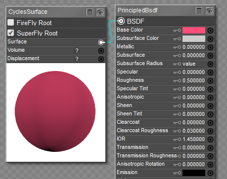 Using the Color chip for color input.
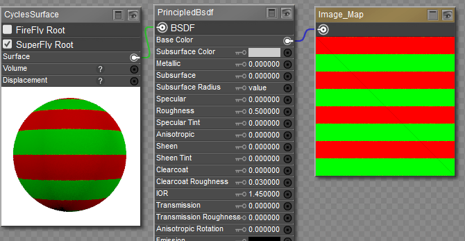 Using a Color Map for color input.
Subsurface Color, Subsurface, Subsurface Radius, and SSS Method
The following screen shot shows how to connect subsurface scattering to the Principled Surface node. The first example shows SSS combined with specular and bump maps. Note that the Specular map is processed through a Gloss/Spec Conversion compound node. You can find this node in the Poser 12 Content > Runtime > Libraries > Materials > SuperFly > SuperFly Tileable > !Guide library.
 Connections for SSS using Specular and Bump Maps
When adding the Gloss-Spec Conversion node to your scene, use the double checkmark, which will add it to the nodes that area already in the Edit window. If you use the single check-mark or double-click the node, it will completely replace what is already there.
 Connections for SSS using Roughness and Normal maps
The connections relating to Subsurface Scattering are as follows:
- Subsurface Color: You can either click the color chip to select the desired subsurface color, or plug in a texture map. In the following example I use an HSV2 node to lighten and slightly saturate the base color map, and then plug the output of the HSV2 node into the Subsfurface Color input of the Principled BSDF node. This is a "one size fits all" solution that should work with most skin colors.
- Subsurface: The strength of the SSS effect. A setting of 0 turns SSS off in the material. Shown in the following example set to 1.
- Subsurface Radius: A tuple value that specifies the Red, Green, and Blue scattering distances in millimeters. The following chart may be helpful in choosing settings that are appropriate for the type of material you are creating.
| Material | Subsurface Radius (R, G, and B values) Distance is in mm |
| Apple | .00696, .00640, .00190 |
| Chicken1 | .01161, .00388, .00175 |
| Chicken2 | .00944, .00335, .00179 |
| Cream | .01503, .00466, .00254 |
| Ketchup | .00476, .00058, .00039 |
| Marble | .00851, .00557, .00395 |
| Potato | .01427, .00723, .00204 |
| Skim Milk | .01842, .01044, .00350 |
| Skin1 (Darker Skin) | .00367, .00137, .00068 |
| Skin2 (Lighter Skin) | .00482, .00169, .00109 |
| Whole Milk | .01090, .00658, .00251 |
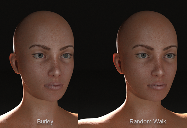
- SSS Method: Choices are Burley or Random Walk.
Scatter Group ID
The Scatter Group ID can be used to prevent bleeding between two materials that have different scattering properties. For example, you might assign all skin materials to one scatter ID, and other areas like lips, eyes, or nails to other scatter group IDs.
Metallic
Metallic inputs can either be a fixed value between 0 and 1 (with 0 being non-metallic and 1 being metallic), or a black and white texture map that identifies non-metallic areas in black and metallic areas in white. For an example of metallic maps connected to the PrincipledBsdf node, see Kitty2 Textures-Principled or Kitty3 Textures-Principled. Metallic texture maps should be set to a Custom Gamma Value of 1.0.
Specular and Specular Tint
The Specular value or image map determines the amount of reflection in non-metallic surfaces. Recommended setting for non-metallic materials is .5.
The Specular Tint value tints the specular reflection using the base color while glancing reflections remain white. The Specular Tint parameter is not physically correct because normally non-metallic materials have colorless reflection. However, it can be used to fake the appearance of materials that have a complex surface structure.
Roughness
Roughness inputs can either be a fixed value between 0 and 1 (with 0 being very glossy and 1 having a matte finish), or a grayscale texture map that identifies more glossy areas in darker shades and more matte areas in lighter shades. For an example of roughness maps connected to the PrincipledBsdf node, see Kitty2 Textures-Principled or Kitty3 Textures-Principled. Roughness texture maps should be set to a Custom Gamma Value of 1.0.
Anisotropic, Anisotropic Rotation, and Tangent
The Anisotropic affects specular reflections. Higher values give elongated highlights along the tangent direction. Negative values shape the highlights perpendicular to the tangent direction.
The Anisotropic Rotation setting rotates the direction of tne elongation such that values of 0 to 1 correspond to angles of 0 to 360. Enter a value of .25 for 90 degree rotation, for example.
The Tangent setting controls the tangent for the Anisotropic layer. Enter a tuple that represents X, Y, and Z coordinates, each value separated by a comma.
Sheen and Sheen Tint
Use the Sheen and Sheen Tint inputs to add a soft reflection near the edges of fabrics. The Sheen setting controls the amount of reflection, and the Sheen Tint setting controls the amount that the base color is mixed with white for sheen reflection.
Clearcoat, Clearcoat Roughness, and Clearcoat Normal
Clearcoat provides an extra white specular layer on top of the other layers. It is typically used for car paint and similar materials. As a example, if you want to create a metallic surface tthat has a clearcoat layer, set Metallic to 1, set Roughness to around .4, and set Clearcoat to 1.
The Clearcoat Roughness input controls the roughness of the clearcoat layer. You can plug a Roughness texture into the Clearcoat Roughness input to add scratches to the clearcoat layer, for example.
The Clearcoat Normal setting controls the normals in the Clearcoat layer. You can use a normal map or a bump map to raise or lower surfaces in the clearcoat layer.
IOR
IOR is the Index of Refraction value for light transmission, typically used with glass and metallic surfaces. Refractive indexes for many common materials can be found on Wikipedia's List of Refractive Indices page.
Transmission and Transmission Roughness
A Transmission setting of 0 is used for a fully opaque surface. A Transmission setting of 1 is used for a fully glass surface.
Emission
High emission values produce more light emission from the material. An emission value of 0 makes a material non-emissive. You can also use a grayscale texture map that identifies non-emissive and emissive areas in a texture map. For an example of emissive maps connected to the PrincipledBsdf node, see Kitty3 Textures-Principled. Emissive texture maps should be set to a Custom Gamma Value of 1.0.
Alpha
The Alpha input setting controls the transparency of the surface. You can enter a numerical value of 0 for fully transparent, or 1 to fully opaque.
To use an image texture with the Alpha input, you can attach an image that has an alpha channel. However, this method only works when you use a Cycles image map texture node (New Node > Cycles > Texture > ImageTexture).
The following example shows a PNG of red dots. The background of the image is transparent, and the image is saved as a PNG with Transparency in Photoshop, giving it an alpha channel. In this example, you connect the Color output of the Cycles image texture to the Base Color input of the PrincipledBSDF node to create the red dots, and connect the Alpha output of the Cycles image texture to the Alpha input of the PrincipledBSDF node to create the transparent areas.
 Use the Cycles image map node to connect images with Alpha channels to the Alpha input of the Principled node
Normal
Normal inputs can either be a fixed tuple value representing X, Y and Z coordinates, or a tangent space OpenGL normal map. The normal map defines raised and lowered areas in the surface. For an example of normal maps connected to the PrincipledBsdf node, see Kitty2 Textures-Principled or Kitty3 Textures-Principled. Normal texture maps should be set to a Custom Gamma Value of 1.0.
Distribution
Selects the type of microfacet distribution to use for the material:
- Burley: Is an approximation to physically-based volume scattering.
- Random Walk: Provides the most accurate results for thin and curved objects. This comes at the cost of increased render time or noise for more dense media like skin, but also better geometry detail preservation. Random Walk uses true volumetric scattering inside the mesh, which means that it works best for closed mesh