Material Nodes
•Math Nodes
•Lighting Nodes
•Variable Nodes
•3D Texture Nodes
•Ray Trace Nodes
•2D Texture Nodes
Math Nodes
These are the math nodes included with Poser. You will find them in the New Node > Math submenu. Unless specified otherwise, the list of attributes for each node is listed from top to bottom.
Blender
The Blender node blends two colors using a value attribute as an alpha mask. It has the following attributes:
.jpg)
Blender Node.
•Input 1: The Input_1 attribute defines the first blend color. Clicking this attribute opens the standard Color Picker.
•Input 2: The Input_2 attribute defines the second blend color. Clicking this attribute opens the standard Color Picker.
•Blending: The Blending attribute is used to determine the amount of blending. Valid values are from 0 (Input 1 color only) to 1 (Input 2 color only).
Color Math (Color_Math)
The Color Math node performs the selected mathematical operation with two colors. It has the following attributes:
.jpg)
Color Math node.
•Math Argument: This pull-down menu defines the math function to be used. Your options are:
•Add: Selecting Add returns Value 1 plus Value 2.
•Subtract: Selecting Subtract returns Value 1 minus Value 2.
•Multiply: Selecting Multiply returns Value 1 times Value 2.
•Divide: Selecting Divide returns Value 1 divided by Value 2.
•Sine: Selecting Sin returns the sine of Value 1. Value 2 is ignored.
•Cosine: Selecting Cos returns the cosine of Value 1. Value 2 is ignored.
•Tangent: Selecting Tan returns the tangent of Value 1. Value 2 is ignored.
•Square Root: Selecting Sqrt returns the square root of Value 1. Value 2 is ignored.
•Power: Selecting Pow returns the Value 1 to the Value 2 power (such as 33).
•Exponential: Selecting Exp returns e to the exponent Value 1, Value 2 is ignored (such as eV1).
•Logarithm: Selecting Log returns the natural log of Value 1, Value 2 is ignored.
•Modulus: Selecting Mod returns the modulus (remainder) of Value 1 divided by Value 2.
•Absolute: Selecting Abs returns the absolute value of Value 1. Value 2 is ignored.
•Sign: Selecting Sign returns –1 if Value 1 is less than zero, and 1 if Value 1 is greater than or equal to zero. Value 2 is ignored.
•Minimum: Selecting Min returns Value 1 if Value 1 is less than Value 2, otherwise Value 2 is returned.
•Maximum: Selecting Max returns Value 1 if Value 1 is greater than Value 2, otherwise Value 2 is returned.
•Clamp: Selecting Clamp returns Value 1 unless Value 1 is less than 0 or greater than
1.If Value 1<0, 0 is returned. If Value 1 > 1, 1 is returned. Value 2 is ignored.
•Ceiling: Selecting Ceil returns Value 1 rounded up to the next whole number. Value 2 is ignored.
•Floor: Selecting Floor returns Value 1 rounded down to the last whole number. Value 2 is ignored.
•Round: Selecting Round returns Value 1 rounded to the nearest whole number. Value 2 is ignored.
•Step: Selecting Step returns 1 if Value 1 is less than or equal to Value 2, and 0 if Value 1 is greater than Value 2.
•Smooth Step: Selecting Smoothstep returns Value 1 bicubically smoothed. Value 2 is ignored.
•Bias: Selecting Bias adjusts the bias of Value 1 by Value 2.
•Gain: Selecting Gain adjusts the gain of Value 1 by Value 2.
•Value 1: The Value_1 attribute defines the first color value in the math equation.
•Value 2: The Value_2 attribute defines the second color value in the math equation.
Color Ramp (ColorRamp)
The Color Ramp node takes four colors and creates a spline color map (gradient) with them. You can feed grayscale output from other nodes (turbulence, wood, etc.) into this node to create interesting still or animated effects using the grayscale values as lookups into the color spline, providing a colorized version of the original grayscale image. It has the following attributes:
.jpg)
Color Ramp node.
•Color 1 through Color 4: The Color_1 through Color_4 attributes allow you to input colors for the color spline. Clicking them opens the standard Color Picker.
•Input: The Input attribute is the grayscale value to lookup into the color spline. This is where you should plug in your grayscale images.
Component (Comp)
The Component node is useful for extracting the red, green, or blue components from an input color. It has the following attributes:
.jpg)
Source image connected to 3 Component Nodes for Red, Green, and Blue respectively.
•Component: The Component attribute specifies the color to extract. 0=red, 1=green, and 2=blue.
•Color: The Color attribute provides an input for another node, whose output will be processed according to the Component attribute setting.
•Point: The Point attribute provides an input for a point node whose output will be processed according to the Component attribute setting.
Edge Blend (Edge_Blend)
The Edge Blend node blends color nodes based on surface and camera angles. It has the following attributes:
.jpg)
Edge Blend Node.
•Inner Color: The Inner Color attribute defines the color of surfaces facing towards the camera. Clicking it opens the standard Color Picker.
•Outer Color: The Outer Color attribute defines the color of surfaces facing away from the camera. Clicking it opens the standard Color Picker.
•Attenuation: The Attenuation attribute defines the power curve used for transitioning between the inner and outer colors.
Fresnel Blend (Fresnel_Blend)
The Fresnel Blend node has the following attributes:
.jpg)
Fresnel Blend Node.
•Outer Color: The Outer Color attribute defines the color of surfaces facing away from the camera. Clicking it opens the standard Color Picker.
•Inner Color: The Inner Color attribute defines the color of surfaces facing towards the camera. Clicking it opens the standard Color Picker.
•Index of Refraction: The index of refraction of the material. Light hitting the surface will be reflected or transmitted dependent on the incident angle based on the index of refraction.
Gamma
The Gamma node allows you to incorporate Gamma settings into the currently selected material. The Gamma node provides the following settings:
.jpg)
Gamma Node.
•Color: Allows you to specify a solid color, or to input other nodes as a source of color.
•Inverse: Used as a shortcut that applies the specified gamma value in reverse. For example, if Gamma value is set to 2.2, checking the Inverse option will result in a Gamma setting of 1/2.2 (or .4545).
•Use Custom Gamma: Check this option to pass the custom gamma settings to the node that is connected to the output.
•Gamma: Sets the desired gamma value.
HSV/HSV2
The HSV and HSV2 nodes allow you to adjust the Hue, Saturation, and/or Value of the Color input. This HSV node scales (ie: multiplies) hue according to the value on the input.
There are two HSV nodes to choose from:
•HSV multiplies Hue, Saturation, and Value with their respective channel values to produce the output color.
•HSV2 adds the Hue value to the channel value, and multiplies Saturation and Value with their respective channel values to produce the output color.
HSV2 is the recommended choice for users that expect Hue to be shifted, as in a circle of colors on a color wheel.
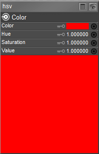
HSV Node.
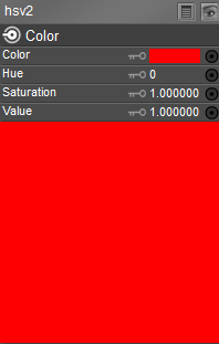
HSV2 Node.
•Color: Allows you to specify the color source that you want to adjust.
•Hue: This attribute allows you to adjust the Hue of the Color input. A setting of 1 represents no adjustment. Increase or decrease the setting to offset the original hue.
•Saturation: This attribute allows you to adjust the Saturation of the Color input. A setting of 1 represents no adjustment. Increase or decrease the setting to offset the original saturation.
•Value: This attribute allows you to adjust the Value of the Color input. A setting of 1 represents no adjustment. Increase or decrease the setting to offset the original value.
Math Functions (Math_Functions)
The Math Functions node is useful for mathematically merging values, nodes, and other parameters and can be used to create patterns. It has the following attributes:
.jpg)
Math Functions Node.
•Math Argument: This pull-down menu defines the math function to be used. Your options are:
•Add: Selecting Add returns Value 1 plus Value 2.
•Subtract: Selecting Subtract returns Value 1 minus Value 2.
•Multiply: Selecting Multiply returns Value 1 times Value 2.
•Divide: Selecting Divide returns Value 1 divided by Value 2.
•Sine: Selecting Sin returns the sine of Value 1. Value 2 is ignored.
•Cosine: Selecting Cos returns the cosine of Value 1. Value 2 is ignored.
•Tangent: Selecting Tan returns the tangent of Value 1. Value 2 is ignored.
•Square Root: Selecting Sqrt returns the square root of Value 1. Value 2 is ignored.
•Power: Selecting Pow returns the Value 1 to the Value 2 power (such as 33).
•Exponential: Selecting Exp returns e to the exponent Value 1, Value 2 is ignored (such as eV1).
•Logarithm: Selecting Log returns the natural log of Value 1, Value 2 is ignored.
•Modulus: Selecting Mod returns the modulus (remainder) of Value 1 divided by Value 2.
•Absolute: Selecting Abs returns the absolute value of Value 1. Value 2 is ignored.
•Sign: Selecting Sign returns –1 if Value 1 is less than zero, and 1 if Value 1 is greater than or equal to zero. Value 2 is ignored.
•Minimum: Selecting Min returns Value 1 if Value 1 is less than Value 2, otherwise Value 2 is returned.
•Maximum: Selecting Max returns Value 1 if Value 1 is greater than Value 2, otherwise Value 2 is returned.
•Clamp: Selecting Clamp returns Value 1 unless Value 1 is less than 0 or greater than
1.If Value 1<0, 0 is returned. If Value 1 > 1, 1 is returned. Value 2 is ignored.
•Ceiling: Selecting Ceil returns Value 1 rounded up to the next whole number. Value 2 is ignored.
•Floor: Selecting Floor returns Value 1 rounded down to the last whole number. Value 2 is ignored.
•Round: Selecting Round returns Value 1 rounded to the nearest whole number. Value 2 is ignored.
•Step: Selecting Step returns 1 if Value 1 is less than or equal to Value 2, and 0 if Value 1 is greater than Value 2.
•Smooth Step: Selecting Smoothstep returns Value 1 bicubically smoothed. Value 2 is ignored.
•Bias: Selecting Bias adjusts the bias of Value 1 by Value 2.
•Gain: Selecting Gain adjusts the gain of Value 1 by Value 2.
•Value 1: The Value_1 value defines the first value in the math equation.
•Value 2: The Value_2 value defines the second value in the math equation.
Simple Color (Simple_Color)
The Simple Color node allows you to access a color picker to select a color. Clicking the color
(Color attribute) opens the Poser Color Picker. To use your operating system’s Color Picker, press [OPT]/[ALT] while clicking the color or click the red-green-blue button in the top right of the Poser Color Picker.
.jpg)
Simple Color node.
User Defined (User_Defined)
The User Defined node allows you to define a custom color. The Color Mode (bottom) attribute is a pull-down menu allowing you to specify your desired color model. You can choose RGB, HSV, or HSL modes and enter the appropriate attributes in the three fields above, as follows:
.jpg)
User Defined node.
•Red: This attribute allows you to specify the first value: Red (RGB) or Hue (HSV or HSL).
•Green: This attribute allows you to specify the second value: Green (RGB) or Saturation (HSV or HSL).
•Blue: This attribute allows you to specify the third value: Blue (RGB) or Value (HSV) or Lightness (HSL).
•Color Mode: This attribute allows you to specify the color mode that applies to the Red, Green, and Blue setting. Choices are RGB (Red, Green, Blue), HSV (Hue, Saturation, Value) or HSL (Hue, Saturation, Lightness.
Lighting Nodes
These are the light nodes included with the Material room. Unless specified otherwise, the list of attributes for each node is listed from top to bottom. The Light menu item has several sub- menus, each containing one or more nodes.
When using lighting nodes with SuperFly, they can only be plugged into Blender or Fresnel Blend nodes, and Alt Diffuse, Specular Color, Reflection Color, or Refraction Color inputs.
•Specular Nodes
•Diffuse Nodes
•Special Nodes
•Environment Map Nodes
Diffuse Nodes Clay
The Clay node applies a clay-like lighting model to the selected material. It has the following attributes:
.jpg)
Clay node.
•Color: The Color attribute specifies the clay color. Clicking the color opens a Color Picker.
•Kd: The Kd attribute specifies the strength of the color, where 1=100%.
•Roughness: The Roughness attribute defines the size of highlights.
Diffuse
The Diffuse node allows you to use the standard diffuse lighting model. It has the following attributes:
.jpg)
Diffuse node.
•Diffuse_Color: The Diffuse_Color attribute specifies the diffuse color.
•Diffuse_Value: The Diffuse_Value attribute defines the strength of the diffuse color, where 1=100%.
•Normals_Forward: Checking the Normals_Forward checkbox will flip the surface normal to point towards the camera (or towards the ray in case of raytracing). Use this option to avoid shading artifacts on double-sided polygons.
ProbeLight
The ProbeLight node takes an irradiance environment map, which is a 360 degree light distribution contained within a single image map, and applies it to your material. It has the following attributes, as well as nine coefficients:
.jpg)
Probe Light node.
•Exposure: The Exposure attribute specifies the brightness, or exposure level, of the irradiance map.
•Saturation: The Saturation attribute specifies the degree of color saturation within the irradiance map.
•SurfaceColor: The SurfaceColor attribute allows you to select a color tint by which the irradiance map will be multiplied. For more realistic results, you should multiply with white.
If your intention is to create an image based light, you can do so by simply adding a diffuse image Based light to your scene in the lighting controls. See Lighting for more information about adding and configuring lights.
Toon
The Toon node gives your material a cartoon-like look. It has the following attributes:
.jpg)
Toon node.
•Light Color: The LightColor attribute specifies the light color.
•Dark Color: The DarkColor attribute specifies the dark color.
•Ink Color: The InkColor attribute specifies the ink color.
•Spread: The Spread attribute defines the sharpness/softness of edges between colors.
•Line Width: the LineWidth attribute specifies the width of the ink color.
•Normals_Forward: Checking the Normals_Forward checkbox will flip the surface normal to point towards the camera (or towards the ray in case of raytracing). Use this option to avoid shading artifacts on double-sided polygons.
•Outline Mode: Specify the type of toon outline that you want to use.
•Original: Uses the version that was initially shipped. Provided for backward compatibility with existing toon shaders.
•Improved: Uses the improved outline method.
![]()
Environment Map Nodes Sphere Map (Sphere_Map)
The Sphere Map node is a lighting node for performing spherical reflections. Attach this node to a materials’ reflection input (or as a raytrace reflection mode’s color attribute) to create spherical reflections. This node has the following attributes:
.jpg)
Sphere map node.
•Color: The Color attribute specifies the map’s color. Clicking the color opens a Color Picker.
•Rotation: The Rotation attribute specifies the maps, rotation along the X, Y, and Z values.
Special Nodes Custom Scatter (Custom_Scatter)
This node exposes subsurface scattering with the raw parameters available to the user, as opposed to the measured presets in the plain Scatter node.
.jpg)
Custom Scatter node.
The Custom Scatter node has the following attributes:
•Surface Color: The overall color of the surface. Applied post-scattering, so textures applied to this input will remain sharp.
•Scatter Color: The color of the light that gets scattered in the material.
•Mean Free Path: The mean distance that light travels in the surface before it scatters.
Larger values result in a more translucent effect. Note that regardless of the settings in
the preferences, this parameter’s units are always in millimeters, due to the small size of typical values.
•IOR (Index of Refraction): The index of refraction of the material. Light hitting the surface will be reflected or transmitted dependent on the incident angle based on the index of refraction. Range is 0.0001 – 3.4.
•Pre-Scatter Color: The incoming light on the surface will be modulated by this color before it scatters in the material.
•Pre-Scatter Ambient: The amount of self-illumination of the material. This is being applied before scattering, so the illumination generated here will be scattered around in the material.
•Max Error: Same parameter as in the other two subsurface scattering nodes, this one is a speed vs. quality trade-off parameter. Lower values equal a more precise calculation at the expense of render time, higher values render faster but may show artifacts. Range is 0.0 – 1.0.
•Scatter Group: Materials with the same scatter group will appear as one surface to scattering. Materials in separate scatter groups are considered separated. See sample render under Scatter.
•Subsurface Method: Selects the type of microfacet distribution to use for the material:
•Burley: Is an approximation to physically-based volume scattering.
•Walk: Provides the most accurate results for thin and curved objects. This comes at the cost of increased render time or noise for more dense media like skin, but also better geometry detail preservation. Random Walk uses true volumetric scattering inside the mesh, which means that it works best for closed mesh.
•Walk Fixed: Provides accurate results for thin and curved objects. Uses true volumetric scattering inside the mesh. Works best for closed meshes. Overlapping faces and holes in the mesh can cause problems.
FastScatter
The FastScatter node offers an easy application of subsurface scattering (SSS) effects. The results of the FastScatter calculation approximate true Subsurface Scattering.
.jpg)
Fast Scatter node.
Subsurface scattering simulates the interaction of light with translucent materials, whereby the light interacts to some degree with the material below the surface level. The FastScatter node is a legacy node that was introduced prior to the implementation of true Subsurface Scattering. This node should be phased out by content developers and replaced with one of the true Subsurface Scattering nodes: Subsurface Skin or Scatter.
The FastScatter node has the following attributes:
•Color: The overall color of the surface. Applied post-scattering, so textures applied to this input will remain sharp.
•Material: Choose from None, Light, or Strong.
•Scatter Group: Materials with the same scatter group will appear as one surface to scattering. Materials in separate scatter groups are considered separated. See sample render under Scatter.
•Subsurface Method: Selects the type of microfacet distribution to use for the material:
•Burley: Is an approximation to physically-based volume scattering.
•Walk: Provides the most accurate results for thin and curved objects. This comes at the cost of increased render time or noise for more dense media like skin, but also better geometry detail preservation. Random Walk uses true volumetric scattering inside the mesh, which means that it works best for closed mesh.
•Walk Fixed: Provides accurate results for thin and curved objects. Uses true volumetric scattering inside the mesh. Works best for closed meshes. Overlapping faces and holes in the mesh can cause problems.
Hair
The Hair node allows you to color your characters’ or props’ strand-based hair. Hair generated in Poser’s Hair room uses this node. It has the following attributes:
.jpg)
Hair node.
•Root Color: The Root_Color attribute selects the color for the root of the hair. Clicking this attribute opens a standard Color Picker.
•Tip Color: The Tip_Color attribute selects the color for the tip of the hair. Clicking this attribute opens a standard Color Picker.
•Specular Color:: The Specular_Color attribute selects the hair’s highlight color. Clicking this attribute opens a standard Color Picker.
•Highlight Size: Allows you to determine the size and intensity of the highlights in the hair.
•Root Softness: The Root_Softness attribute controls the root’s transparency, which helps hair blend into the scalp.
(1).png)
•Opaque in Shadow: Check this option to create solid shadows beneath hair strands. This allows you to create hair that looks more full without having to increase the number of hairs on the head (thereby requiring less computer resources).
![]()
Scatter
The Scatter node offers another way to render scattering effects in various objects, including skin. A number of presets that use real-world material properties are included in this node.
The Scatter node is depreciated and may be dropped in future versions of Poser. It uses an outdated scatter model. It's been revised as much as possible to produce similar results to previous versions for Poser 13. The Scatter node may not produce expected results using the "Walk" and "Walk Fixed" Subsurface methods. It's recommended to use the scatter setting in the Physical Root node or the Custom Scatter node instead.
The Scatter node offers the following settings:
.jpg)
Scatter node.
•Material: The Material selector includes several presets that emulate the scatter effects of real-world materials.
.jpg)
Material options.
•Use Material Color: Check this option if you want to use color from the Material property.
•Texture Detail: Represents the ratio of the use of the texture for post-scatter versus pre- scatter. The range is from 0-1.0. A value of 1 will apply 100% of texture at post-scatter, yielding more texture details. A value 0 uses none of texture at post-scatter, applying all of that texture for pre-scatter calculations, and yields very low texture detail. A value of .5 is a reasonable point to start experimenting.
•Scale: Each of the Scatter materials are based on physical measurements. The Scale setting decreases or increases the physical scale to adjust appropriately for your geometry in the event that it is smaller or larger than it would be in real life.
•MaxError: This setting is a quality-speed trade-off. When set to a low value, you will get higher precision in the subsurface scattering, but rendering will be more slow. When set to a higher value, you will get better rendering speeds, but less precision in the subsurface scattering.
•Color: Determines the base color for the material. The Scatter effect is added to this color. By default it is set to white. You can choose another color or add an image map or other node to the input.
•Scatter Group: Materials with the same scatter group will appear as one surface to scattering. Materials in separate scatter groups are considered separated. In the image that follows, the two spheres on the left are in the same scatter group. The sphere on the right is a different scatter group.
•Subsurface Method: Selects the type of microfacet distribution to use for the material:
•Burley: Is an approximation to physically-based volume scattering.
•Walk: Provides the most accurate results for thin and curved objects. This comes at the cost of increased render time or noise for more dense media like skin, but also better geometry detail preservation. Random Walk uses true volumetric scattering inside the mesh, which means that it works best for closed mesh.
•Walk Fixed: Provides accurate results for thin and curved objects. Uses true volumetric scattering inside the mesh. Works best for closed meshes. Overlapping faces and holes in the mesh can cause problems.
.png)
Scatter Groups
It is beneficial to place teeth or eyeballs in a different scatter group than the skin on the face. This prevents light from scattering between them.
Skin
The Skin node allows you to create realistic skin. It has the following attributes:
.jpg)
Skin node.
•Skin Color: The SkinColor attribute selects the skin’s base color. Clicking this attribute opens a standard Color Picker.
•Sheen Color: The SheenColor attribute is the color of any highlight that appears on the object surface. Highlights lend the illusion of shininess. For example, a piece of wood displays no highlight, while a piece of polished metal has one or more distinct highlights. This color is generally the same as that of the direct lighting falling on the affected surface but does not have to be.
•Ka: The Ka attribute controls the ambient light strength, where 1=100%.
•Kd: The Kd attribute controls the diffuse light strength, where 1=100%.
•Ks: The Ks attribute controls the specular light strength, where 1=100%.
•Thickness: The Thickness attribute controls the thickness of the top, translucent skin layer.
•ETA: The ETA attribute controls the density of the top, translucent skin layer.
Subsurface Skin
The Subsurface Skin node offers more realistic skin effects than the Skin node. It adds subsurface scattering effects that give the skin more luminescence and sheen. This node has the following settings:
.jpg)
Subsurface Skin node.
•Color: Determines the base color for the material. The Subsurface Skin effect is added to this color. By default it is set to white. You can choose another color, or attach an image map or another node to the input.
•Texture Detail: Represents the ratio of the use of the texture for post-scatter versus pre- scatter. The range is from 0-1.0. A value of 1 will apply 100% of texture at post-scatter, yielding more texture details. A value 0 uses none of texture at post-scatter, applying all of that texture for pre-scatter calculations, and yields very low texture detail. A value of .5 is a reasonable point to start experimenting.
•Specularity: When set to 1, this setting approximates the physical specular behavior of human skin. Increase or decrease the setting for your desired effect.
•Highlight Size: Determines the size of the highlight, similar to the way that Highlight Size works in the Root node.
•MaxError: This setting is a quality-speed trade-off. When set to a low value, you will get higher precision in the subsurface scattering, but rendering will be more slow. When set to a higher value, you will get better rendering speeds, but less precision in the subsurface scattering.
•Scatter Group: Materials with the same scatter group will appear as one surface to scattering. Materials in separate scatter groups are considered separated. See sample render under Scatter.
•Subsurface Method: Selects the type of microfacet distribution to use for the material:
•Burley: Is an approximation to physically-based volume scattering.
•Walk: Provides the most accurate results for thin and curved objects. This comes at the cost of increased render time or noise for more dense media like skin, but also better geometry detail preservation. Random Walk uses true volumetric scattering inside the mesh, which means that it works best for closed mesh.
•Walk Fixed: Provides accurate results for thin and curved objects. Uses true volumetric scattering inside the mesh. Works best for closed meshes. Overlapping faces and holes in the mesh can cause problems.
In order to use the Subsurface Skin node, the Subsurface Scattering option must be turned on in Firefly’s Render Settings tab.
.jpg)
Firefly Render Settings dialog with Subsurface Scattering turned on.
Go to the Material room and select the Head material. Right-click in an empty area in the Edit material view and choose New Node > Lighting > Special > Subsurface Skin.
Plug the output of the image map into the Color input of the new node. Then, plug the output of the new node into the Alternate Diffuse input of the PoserSurface root node. Finally, set the Diffuse Value setting in the root node to 0, so that Poser only uses the ALT Diffuse setting.
.jpg)
Material Settings for the Subsurface Skin node.
When you render the new material in FireFly, Poser will first render a pre-pass to calculate light all over the surface (including the back side). During the second pass, it calculates the scattering. The figure above shows results rendered in SuperFly
Velvet
The Velvet node allows you to create the appearance of realistic velvety fabric. It has the following attributes:
.jpg)
Velvet node.
•Velvet Color: The Velvet_Color attribute selects the color. Clicking this attribute opens a standard Color Picker.
•Velvet Sheen: The Velvet_Sheen attribute is the color of any highlight that appears on the object surface. Highlights lend the illusion of shininess. For example, a piece of wood displays no highlight, while a piece of polished metal has one or more distinct highlights. This color is generally the same as that of the direct lighting falling on the affected surface but does not have to be.
•Ka: The Ka attribute controls the ambient light strength, where 1=100%.
•Kd: The Kd attribute controls the diffuse light strength, where 1=100%.
•Ks: The Ks attribute controls the specular light strength, where 1=100%.
•Roughness: The Roughness attribute controls the thickness of the velvet.
•Edginess: This attribute controls the horizon scatter of the velvet.
•Normals_Forward: Checking the Normals_Forward checkbox will flip the surface normal to point towards the camera (or towards the ray in case of raytracing). Use this option to avoid shading artifacts on double-sided polygons.
Volume
.jpg)
Volume node.
•Absorption Color: The color of the light that is absorbed by the volume material.
•Absorption Density: How much of the light interacts with absorption.
.jpg)
Absorption Color example.
•Scatter Color: The color of the light that is scattered from the volume material.
•Scatter Density: How much of the light interacts with volume scattering.
•Scatter Anisotropy: The direction in which the light is most likely to scatter.
.jpg)
Scatter Color example.
•Emission Color: The color of light that is emitted from the volume.
•Emission Strength: The strength of the emission color.
.jpg)
Emission Color example.
Specular Nodes
Specular nodes provide different models for calculating highlights on objects.
Anisotropic
The Anisotropic node allows you to create irregularly shaped highlights. It has the following attributes:
.jpg)
Anisotropic node.
•Specular Color: The Specular_Color is the color of any highlight that appears on the object surface. Highlights lend the illusion of shininess. For example, a piece of wood displays no highlight, while a piece of polished metal has one or more distinct highlights. This color is generally the same as that of the direct lighting falling on the affected surface but does not have to be.
•Specular Value: The Specular_Value is the amount of influence the specular color has on the shader. A higher value will create larger, more distinct highlights and vice versa.
•U Highlight Size: The U_Highlight_Size attribute is the highlight’s size in the U direction.
•V Highlight Size: The V_Highlight_Size attribute is the highlight’s size in the V direction.
•Rotation: Specify the rotation of the specular node.
•Normals_Forward: Checking the Normals_Forward checkbox will flip the surface normal to point towards the camera (or towards the ray in case of raytracing). Use this option to avoid shading artifacts on double-sided polygons.
Blinn
The Blinn node defines a model for calculating highlights. It has the following attributes:
.jpg)
Blinn node.
•Specular Color: The Specular_Color is the color of any highlight that appears on the object surface. Highlights lend the illusion of shininess. For example, a piece of wood displays no highlight, while a piece of polished metal has one or more distinct highlights. This color is generally the same as that of the direct lighting falling on the affected surface but does not have to be.
•Eccentricity: The Blinn formula models the microfacets (microscopic imperfections) of the surface as ellipsoids of revolution. The Eccentricity attribute controls the size and variation of the imperfections. Use 0 for very shiny surfaces and 1 for very diffuse surfaces.
•Specular Roll Off: The SpecularRollOff attribute controls the highlight’s sharpness.
•Reflectivity: The Reflectivity attribute controls the amount of light reflected back to the eye.
•Normals_Forward: Checking the Normals_Forward checkbox will flip the surface normal to point towards the camera (or towards the ray in case of raytracing). Use this option to avoid shading artifacts on double-sided polygons.
Glossy
The Glossy node defines a model for calculating highlights. It has the following attributes:
.jpg)
Glossy node.
•Specular Color: The Specular_Color is the color of any highlight that appears on the object surface. Highlights lend the illusion of shininess. For example, a piece of wood displays no highlight, while a piece of polished metal has one or more distinct highlights. This color is generally the same as that of the direct lighting falling on the affected surface but does not have to be.
•Ks: The Ks attribute defines the strength of the specular color, where 1=100%.
•Roughness: The Roughness attribute defines the size of highlights.
•Sharpness: The Sharpness attribute defines the sharpness of the highlight’s edge.
•Normals_Forward: Checking the Normals_Forward checkbox will flip the surface normal to point towards the camera (or towards the ray in case of raytracing). Use this option to avoid shading artifacts on double-sided polygons.
ks Microfacet (ks_microfacet)
The KS-Microfacet node is a node that is a physically-based specular node that uses specularity calculations similar to those used in the Subsurface Skin and Scatter nodes.
The settings are as follows:
.jpg)
ks-Microfacet node.
•Specular Color: The Specular_Color is the color of any highlight that appears on the object surface. This color is generally the same as that of the direct lighting falling on the affected surface but does not have to be.
•Roughness: The Roughness attribute defines the size of highlights. Lower values create smaller, sharper highlights. Higher values create larger, more diffused highlights.
•Ks: The Ks attribute controls the specular light strength, where 1=100%. Phong
The Phong node defines a model for calculating highlights. It has the following attributes:
.jpg)
Phong node.
•Specular Color: The Specular_Color is the color of any highlight that appears on the object surface. Highlights lend the illusion of shininess. For example, a piece of wood displays no highlight, while a piece of polished metal has one or more distinct highlights. This color is generally the same as that of the direct lighting falling on the affected surface but does not have to be.
•Specular Value: The Specular_Value is the amount of influence the specular color has on the shader. A higher value will create larger, more distinct highlights and vice versa.
•Size: The Size attribute specifies the size of the highlight.
•Normals_Forward: Checking the Normals_Forward checkbox will flip the surface normal to point towards the camera (or towards the ray in case of raytracing). Use this option to avoid shading artifacts on double-sided polygons.
Specular
The Specular node defines a model for calculating highlights. It has the same attributes as the Phong node, which is discussed below.
.jpg)
Specular node.
•Specular Color:: The Specular_Color is the color of any highlight that appears on the object surface. Highlights lend the illusion of shininess. For example, a piece of wood displays no highlight, while a piece of polished metal has one or more distinct highlights. This color is generally the same as that of the direct lighting falling on the affected surface but does not have to be.
•Specular Value: The Specular_Value is the amount of influence the specular color has on the shader. A higher value will create larger, more distinct highlights and vice versa.
•Roughness: The Roughness attribute defines the size of highlights.
•Normals_Forward: Checking the Normals_Forward checkbox will flip the surface normal to point towards the camera (or towards the ray in case of raytracing). Use this option to avoid shading artifacts on double-sided polygons.
Variable Nodes
These are the value nodes included with Poser. Unless specified otherwise, the list of attributes for each node is listed from top to bottom.
dNdu
The dNdu node represents the derivative of the surface normal in the ‘U’ direction. In other words, it defines the rate of change of the surface normal along ‘U’.
dNdv
The dNdv node represents the derivative of the surface normal in the ‘V’ direction. In other words, it defines the rate of change of the surface normal along ‘V’.
dPdu
The dPdu node represents a varying point surface shader variable. It is a vector perpendicular to the surface normal in the ‘U’ direction. Specifically, it indicates the derivative of the surface position along ‘U’. It has no user-definable attributes.
dPdv
The dPdv node represents a varying point surface shader variable. It is a vector perpendicular to the surface normal in the ‘V’ direction. Specifically, it indicates the derivative of the surface position along ‘V’. It has no user-definable attributes.
Du
The dU node defines the rate of change of surface parameters as pertains to the current pixel’s location in S space. The ‘d’ indicates a derivative of the ‘U’ parameter.
Dv
The dV node defines the rate of change of surface parameters as pertains to the current pixel’s location in T space. The ‘d’ indicates a derivative of the ‘V’ parameter.
Frame Number (frame_number)
The Frame Number node returns the current frame number. It has no user-definable attributes.
N
The N node returns the normal at the specified point. It has the following attributes:
.jpg)
N Node.
•X: The X attribute is the normal vector’s X component.
•Y: The Y attribute is the normal vector’s Y component. • Z: The Z attribute is the normal vector’s Z component.
.jpg)
Visualizes direction of surface normal.
P
The P node defines a point in space. It has the following attributes:
.jpg)
P Node.
•X: The X attribute is the point’s X location.
•Y: The Y attribute is the point’s Y location. • Z: The Z attribute is the point’s Z location.
1.Texture Coordinate (u)
The U node returns the S coordinate in texture space of the pixel currently being rendered. It has no user-definable attributes.
22.Texture Coordinate (v)
The V node returns the T coordinate in texture space of the pixel currently being rendered. It has no user-definable attributes.
3D Texture Nodes
These are the color nodes included with the Material room. Unless specified otherwise, the list of attributes for each node is listed from top to bottom.
Cellular
The Cellular node is used to create mosaic or cubic tiles. It has the following attributes:
.jpg)
Cellular node.
•Color1: The Color1 attribute specifies the cell color.
•Intensity1: The Intensity1 attribute determines the degree of dominance between the cells and the cusps.
•Color2: The Color2 attribute specifies the color of the borders between the cells.
•Intensity2: The Intensity2 attribute determines the degree of dominance between the cells and the cusps.
•ScaleX: The ScaleX attribute controls the size of the tiles along the x axis.
•ScaleY: The ScaleY attribute controls the size of the tiles along the y axis.
•ScaleZ: The ScaleZ attribute controls the size of the tiles along the z axis.
•RandomColor: Enabling the RandomColor attribute specifies that the color of each cell will be randomly determined.
•CellMode: The CellMode attribute determines the type and shape of the cells. It has the following options:
•Mode 1: This option creates 3D tiles. You can increase the Intensity1 value to make the tiles more prominent.
•Mode 2: This option emphasizes the cracks between the cells. Set the Intensity1 value relatively high to maximize this effect.
•Mode 3: This option creates a spider-web effect. The Color1 attribute defines the color of the web strands. Set the Intensity1 value relatively high to maximize this effect.
•Mode 4: This option is similar to that of Mode 3, but it includes an additional dimension.
•Mode 5: This option creates a quilt-style cell pattern when the RandomColor attribute is enabled.
•Jitter: The Jitter attribute controls the irregularity of the cell sizes.
•Turbulence: The Turbulence attribute controls the irregularity of the cell boundaries.
•GlobalCoordinates: When the GlobalCoordinates attribute is enabled, the object will use the global coordinates.
•Noise_Type: The Noise_Type attribute allows you to select between the Original Perlin type and the Improved enhanced noise definitions.
Clouds
The Clouds node simulates cloud patterns. It has the following attributes:
.jpg)
Clouds node.
•Sky Color: The Sky_Color attribute defines the areas behind the clouds. Clicking it opens the standard Color Picker.
•Cloud Color: The Cloud_Color attribute defines the clouds. Clicking it opens the standard Color Picker.
•Scale: The Scale attribute defines the size of the clouds.
•Complexity: The Complexity attribute defines the complexity of the cloud patterns.
•Bottom: The Bottom attribute controls the bottom color level or floor.
•Bias: The Bias attribute specifies how far to shift samples towards the light source to prevent self-shadowing of objects.
•Gain: The Gain attribute controls the balance between light and dark colors.
•Global Coordinates: Use the Global_Coordinates pull-down menu to select ON or OFF. When on, the texture is computes using world space instead of object space and vice versa. If this option is on while the object is moving in any way, the texture will appear to “slide” through the object when rendered.
•Noise_Type: The Noise_Type attribute allows you to select between the Original Perlin type and the Improved enhanced noise definitions.
•Offset X, Y, or Z: Enter the amount of offset desired from default X, Y, and Z position, for animation of 3D texture node.
fBm
The fBm node is a multi-fractal function. It has the following attributes:
.jpg)
fBm node.
•Signed: Checking the Signed checkbox returns values in the range –1 to 1. If unchecked, values less than 0 will be returned unsigned, e.g. –25 will be returned as 25.
•Fractal Increment: The Fractal_Increment attribute controls noise. Lower values result in a smoother noise gradient.
•Frequency Gap: The Frequency_Gap attribute controls fractal size. Higher values product larger fractals.
•Octaves: The Octaves attribute defines the number of iterations for the fractal function. Higher values produce more detailed fractals but may increase render time.
•X Scale: The scale of the property along the X (horizontal) axis
•Y Scale: The scale of the property along the Y (vertical) axis.
•Z Scale: The scale of the property along the Z (depth) axis.
•Bottom: The Bottom attribute controls the bottom color level or floor.
•Bias: The Bias attribute specifies how far to shift samples towards the light source to prevent self-shadowing of objects.
•Gain: The Gain attribute controls the balance between light and dark colors.
•Noise_Type: The Noise_Type attribute allows you to select between the Original Perlin type and the Improved enhanced noise definitions.
•Offset X, Y, or Z: Enter the amount of offset desired from default X, Y, and Z position, for animation of 3D texture node.
Fractal Sum (Fractal_Sum)
The Fractal Sum node is a fractal function that returns values between –1 and 1. It has the following attributes:
.jpg)
Fractal Sum node.
•X Scale: The scale of the property along the X (horizontal) axis
•Y Scale: The scale of the property along the Y (vertical) axis.
•Z Scale: The scale of the property along the Z (depth) axis.
•Octaves: The Octaves attribute defines the number of iterations for the fractal function. Higher values produce more detailed fractals but may increase render time.
•Bottom: The Bottom attribute controls the bottom color level or floor.
•Bias: The Bias attribute specifies how far to shift samples towards the light source to prevent self-shadowing of objects.
•Gain: The Gain attribute controls the balance between light and dark colors.
•Offset X, Y, or Z: Enter the amount of offset desired from default X, Y, and Z position, for animation of 3D texture node.
Granite
The Granite node is a 3D simulation of speckled granite textures. It has the following attributes:
.jpg)
Granite node.
•Base Color: The Base_Color attribute defines the base color. Clicking it opens the standard Color Picker.
•Spot Color: The Spot_Color attribute defines the spot color. Clicking it opens the standard Color Picker.
•Scale: The Scale attribute defines the size of the speckles (spots).
•Shades: The Shades attribute defines the number of shades used for the texture between and including the base and spot colors.
•Balance: The Balance attribute defines the lean towards the base or spot color. Values close to 0 favor the spot color while values closer to 1 favor the base color.
•Global Coordinates: Use the Global_Coordinates pull-down menu to select ON or OFF. When on, the texture is computes using world space instead of object space and vice versa. If this option is on while the object is moving in any way, the texture will appear to “slide” through the object when rendered.
•Noise_Type: The Noise_Type attribute allows you to select between the Original Perlin type and the Improved enhanced noise definitions.
Marble
The Marble node is a 3D simulation of marble or other stone patterns. It has the following attributes:
.jpg)
Marble node.
•Base Color: The Base_Color attribute defines the base color. Clicking it opens the standard Color Picker.
•Veins: The Veins attribute defines the vein color. Clicking it opens the standard Color Picker.
•Scale: The Scale attribute defines the size of the veins.
•Turbulence: The Turbulence attribute defines the low-frequency randomness of the brick pattern.
•Global Coordinates: Use the Global_Coordinates pull-down menu to select ON or OFF. When on, the texture is computes using world space instead of object space and vice versa. If this option is on while the object is moving in any way, the texture will appear to “slide” through the object when rendered.
•Noise_Type: The Noise_Type attribute allows you to select between the Original Perlin type and the Improved enhanced noise definitions.
Noise
The Noise node adds random “static” or “snow” effects. It has the following attributes:
.jpg)
Noise node.
•X Index: The x_index attribute defines the position on the X axis from which to draw a noise sample.
•Y Index: The y_index attribute defines the position on the Y axis from which to draw a noise sample.
•Z Index: The z_index attribute defines the position on the Z axis from which to draw a noise sample.
•Min: The Min attribute controls the minimum amount of noise.
•Max: The Max attribute controls the maximum amount of noise.
Spots
The Spots node consists of a 3D texture composed of random spots. It has the following attributes:
.jpg)
Spots node.
•Base Color: The Base_Color attribute defines the base color. Clicking it opens the standard Color Picker.
•Spot Color: The Spot_Color attribute defines the spot color. Clicking it opens the standard Color Picker.
•Spot Size: The Spot_Size attribute defines the size of the spots.
•Softness: The Softness attribute determines the transition from the spot to the base color.
•Threshold: The Threshold attribute defines the lean towards the base or spot color. Values close to 0 favor the base color while values closer to 1 favor the spot color.
•Global Coordinates: Use the Global_Coordinates pull-down menu to select ON or OFF. When on, the texture is computes using world space instead of object space and vice versa. If this option is on while the object is moving in any way, the texture will appear to “slide” through the object when rendered.
•Noise_Type: The Noise_Type attribute allows you to select between the Original Perlin type and the Improved enhanced noise definitions.
Turbulence
The Turbulence node is an unsigned fractal function. It has the following attributes:
.jpg)
Turbulence node.
•X Scale: The scale of the property along the X (horizontal) axis
•Y Scale: The scale of the property along the Y (vertical) axis.
•Z Scale: The scale of the property along the Z (depth) axis.
•Octaves: The Octaves attribute defines the number of iterations for the fractal function. Higher values produce more detailed fractals but may increase render time.
•Bottom: The Bottom attribute controls the bottom color level or floor.
•Bias: The Bias attribute specifies how far to shift samples towards the light source to prevent self-shadowing of objects.
•Gain: The Gain attribute controls the balance between light and dark colors.
•Noise_Type: The Noise_Type attribute allows you to select between the Original Perlin type and the Improved enhanced noise definitions.
•Offset X, Y, or Z: Enter the amount of offset desired from default X, Y, and Z position, for animation of 3D texture node.
Wave3D
The Wave3D node implements a three-dimensional sin / cos trigonometric function, resulting in a three-dimensional wave effect.
.jpg)
Wave 3D node.
Wood
The Wood node provides a 3D texture that simulates wood patterns. It has the following attributes:
.jpg)
Wood node.
•Light Wood: The Light_Wood attribute defines the base wood color. Clicking it opens the standard Color Picker.
•Dark Wood: The Dark_Wood attribute defines the wood grain color. Clicking it opens the standard Color Picker.
•Scale: The Scale attribute determines the size of the wood grain.
•Turbulence: The Turbulence attribute determines the amount of randomness of the wood grain.
•Global Coordinates: Use the Global_Coordinates pull-down menu to select ON or OFF. When on, the texture is computes using world space instead of object space and vice versa. If this option is on while the object is moving in any way, the texture will appear to “slide” through the object when rendered.
•Noise_Type: The Noise_Type attribute allows you to select between the Original Perlin type and the Improved enhanced noise definitions.
Ray Trace Nodes
To use the raytracing nodes, you must have raytracing enabled in the Render Settings dialog, as described in The Render Settings Dialog.
Ambient Occlusion (Ambient_Occlusion)
The Ambient Occlusion node uses raytracing to calculate the degree to which other objects within a scene mask (or occlude) the ambient light of a surface at a given point. Surfaces with greater occlusion ratios will be rendered as darker than surfaces with little or no occlusion. This node has the following attributes:
.jpg)
Ambient Occlusion node.
•Samples: The Samples attribute determines the number of rays projected. Too few samples will result in a grainy appearance in the darker areas of the scene. Higher sample rates yield higher quality darkened areas, but take longer to render.
•MaxDist: The MaxDist attribute allows you to control the maximum distance that the rays will travel through the scene, thus limiting the amount of data collected.
•RayBias: The RayBias attribute helps to prevent false shadows and other artifacts that may occur as a result of using raytracing techniques in conjunction with displacement maps. RayBias offsets the starting point of the rays above the geometry of the surface, so as to avoid the displacement geometry in the raytracing calculation. Be aware that if your RayBias setting is too high, your shadows will migrate in the scene.
![]()
•Strength: The Strength attribute controls the degree to which the Ambient Occlusion node will darken the occluded surfaces within the scene.
•Evaluate in IDL: Check this option if you want Poser to consider ambient occlusion settings during an indirect lighting pass.
.jpg)
Without Ambient Occlusion (left); With Ambient Occlusion/depth mapped shadows (right).
Fresnel (fresnel)
The Fresnel node is used for surfaces that are both refractive and reflective (also known as dielectrics). Such surfaces tend to reflect more when the observer to surface angle is high, and refract more when the observer to surface angle is low. Most surfaces that are transparent (refractive) are also reflective.
Fresnel node.
To use the Fresnel node with a surface node, plug it into the surface node’s refraction_color channel. Set the Diffuse values low, and Transparency to 0. The Fresnel node has the following attributes:
•Background: The Background attribute selects the background color to be used for raytracing. Clicking this attribute opens a standard Color Picker.
•Index of Refraction: The Index of Refraction attribute controls how much light bends when passing through the object.
•Quality: The Quality attribute controls how many rays are spawned by hitting a surface. Increasing this value increases the realism of reflections but consumes computing resources.
![]()
Softness: The Softness attribute controls how sharp or smooth refracted light appears after passing through an object.
Gather
The Gather node uses raytracing to collect color and light information from the surfaces within a specific area, which when combined with an infinite light source adds a realistic “outdoor” lighting effect. This effect also adds some color bleeding to the rendered scene. The Gather sampling area, or cone, is defined by the following attributes:
.jpg)
Gather node.
•Samples: The Samples attribute determines the number of Gather rays projected. Higher sample rates yield more realistic results, but take longer to render.
•MaxDist: The MaxDist attribute allows you to control the maximum distance that the Gather rays will travel through the scene, thus limiting the amount of data collected.
•RayBias: The RayBias attribute helps to prevent false shadows and other artifacts that may occur as a result of using raytracing techniques in conjunction with displacement maps. RayBias offsets the starting point of the Gather rays above the geometry of the surface, so as to avoid the displacement geometry in the raytracing calculation. Be aware that if your RayBias setting is too high, your shadows will migrate in the scene.
![]()
•Angle: The Angle attribute sets the angle of the cone in which the Gather rays will be projected. A wider angle will result in a greater area and hence more data. More data will give you more realistic results, but longer render times.
.jpg)
Without Gather/no color bleeding (left); With Gather/color bleeding (right).
Reflect
The Reflect node specifies the reflection color when raytracing. It has the following attributes:
.jpg)
Reflect node.
•Background: The Background attribute selects the background color to be used for raytracing. Clicking this attribute opens a standard Color Picker.
•Quality: The Quality attribute controls how many rays are spawned by hitting a surface. Increasing this value increases the realism of reflections but consumes computing resources.
•Softness: The Softness attribute controls the randomness of the directions of reflected rays.
•RayBias: The RayBias attribute helps to prevent false shadows and other artifacts that may occur as a result of using raytracing techniques in conjunction with displacement maps. RayBias offsets the starting point of the rays above the geometry of the surface, so as to avoid the displacement geometry in the raytracing calculation. Be aware that if your RayBias setting is too high, your shadows will migrate in the scene.
![]()
Refract
The Refract node specifies the refraction color when raytracing. It has the following attributes:
.jpg)
Refract node.
•Background: The Background attribute selects the background color to be used for raytracing. Clicking this attribute opens a standard Color Picker.
•Index of Refraction: The Index of Refraction attribute controls how much light bends when passing through the object.
•Quality: The Quality attribute controls how many rays are spawned by hitting a surface. Increasing this value increases the realism of reflections but consumes computing resources.
•Softness: The Softness attribute controls how sharp or smooth refracted light appears after passing through an object.
•RayBias: The RayBias attribute helps to prevent false shadows and other artifacts that may occur as a result of using raytracing techniques in conjunction with displacement maps. RayBias offsets the starting point of the rays above the geometry of the surface, so as to avoid the displacement geometry in the raytracing calculation. Be aware that if your RayBias setting is too high, your shadows will migrate in the scene.
![]()
2D Texture Nodes
These are the color nodes included with the Material room. Unless specified otherwise, the list of attributes for each node is listed from top to bottom.
Brick
The Brick node simulates brick or stone wall patterns. It has the following attributes:
.jpg)
Brick node.
•Brick Color: The Brick_Color attribute defines the brick color. Clicking it opens the standard Color Picker.
•Mortar Color: The Mortar_Color attribute defines the mortar color. Clicking it opens the standard Color Picker.
•Brick Width: The Brick_Width attribute determines the horizontal scale of the bricks.
•Brick Height: The Brick_Height attribute determines the vertical scale of the bricks.
•Mortar Width: The Mortar_Width attribute determines the spacing between bricks.
•Turbulence: The Turbulence attribute defines the low frequency randomness of the brick pattern.
•Softness: The Softness attribute defines how softly the brick blends into the mortar.
•Noise: The Noise attribute defines the high frequency randomness of the brick pattern.
•U Offset: The U_Offset attribute defines the U position of the first texture tile in UV space. When using a projection map method (see below), this is one of two attributes used to define the position of the upper left corner of the projection “screen” in grid units.
•V Offset: The V_Offset attribute defines the V position of the first texture tile in UV space. When using a projection map method (see below), this is one of two attributes used to define the position of the upper left corner of the projection “screen” in grid units.
•Noise_Type: The Noise_Type attribute allows you to select between the Original Perlin type and the Improved enhanced noise definitions.
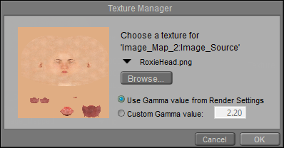
Image Map (Image_Map)
The Image Map node allows you to specify an image to use as a map (texture, reflection, transparency, bump, displacement, etc.). You can use any image as a map. However, if you want to use a map designed for the particular figure/prop, you must use an image that has been set up to work that way. PThis node has the following attributes:
(1).png)
Image map node.
•Image Source: Displays the currently loaded image. Clicking the Image Source attribute opens the Texture Manager dialog. To load an image map, either select the path from the drop-down list or click the Browse button to open a standard Open dialog and select the image you wish to load. A preview of your selected image should appear in the preview window. You can also select to use a global gamma value as set in the Render Settings dialog, or enter a specific gamma value that is unique to the selected texture. Click OK to implement your changes or Cancel to abort.
When creating PBR-type shaders, Diffuse textures typically use the gamma value from Render Settings. All other image types (bump, height, specular, transparency, normal, metal, and roughness) use a Custom Gamma value of 1. Poser tries to automatically assign a custom gamma value of 1 to images when they are dragged and dropped into the material room, based on a recognized suffix in the filename. For example, if the filename ends in _normal or _n, it will detect that it is a normal map and automatically assign a gamma value of 1.
This function recognizes the following words in the filenames, preceded by an underscore character:
_albedo or _a
_bump or _b
_color, _col, or _c
_diffuse or _d
_emissive or _e
_height or _h
_normal or _n
_roughness, _rough, or _r
_specular, _spec, or _s
_transparency, _trans, or _t
•Auto_Fit: Check this option to automatically fit the texture map to the currently selected material without tiling.
•U Scale: The U_Scale attribute sets the U scale factor to apply to the texture map when using UV or VU mapping. When using a projection map method (see below), this is one of two attributes used to define the world space size of the texture map being projected onto the surface.
•V Scale: The V_Scale attribute sets the V scale factor to apply to the texture map when using UV or VU mapping. When using a projection map method (see below), this is one of two attributes used to define the world space size of the texture map being projected onto the surface.
•U Offset: The U_Offset attribute defines the U position of the first texture tile in UV space. When using a projection map method (see below), this is one of two attributes used to define the position of the upper left corner of the projection “screen” in grid units.
•V Offset: The V_Offset attribute defines the V position of the first texture tile in UV space. When using a projection map method (see below), this is one of two attributes used to define the position of the upper left corner of the projection “screen” in grid units.
•Texture Coordinates: The Texture_Coordinates pull-down menu offers the following choices:
•UV: The UV option behaves like rubber wallpaper that can stretch over the object surface; the image file is made to correspond with set positions on the object’s surface, making any distortion caused by the stretching seem more natural. This is the most versatile mapping method.
•VU: The VU option is identical to UV mapping, except that the image map is rotated 90 degrees.
•XY: The XY option works like a slide projector in that the “screen” being projected onto is the XY plane whose size and position are determined using the U_Scale, V_Scale, U_Offset, and V_Offset parameters. Any surface not oriented with the selected viewing plane will distort the texture at render time.
•XZ: Same as above but uses the XZ plane.
•ZY: Same as above but uses the ZY plane.
•Image Mapped: The Image_Mapped pull-down menu offers the following choices:
•None: The background color will be used for all areas of the object not covered by the texture map.
•Alpha: The background color will be used for all areas of the object not covered by the texture map. The background color will also be blended with the texture map based on the alpha channel of the texture map.
•Clamped: The edge pixels of the texture map are repeated to cover any area of the object that the texture map does not cover.
•Tile: The texture map will be tiled to ensure total coverage. Tiling is controlled using the Mirror U and Mirror V attributes, below.
•Background: The Background attribute specifies the background color. Clicking this attribute opens a standard Color Picker. Global_Coordinates button forces projected maps to use global instead of local coordinates.
•Global Coordinates: This option is unused.
•Mirror U: Enabling the Mirror_U option can help hide the seams between texture cells when tiling textures.
•Mirror V: Enabling the Mirror_V option can help hide the seams between texture cells when tiling textures.
•Texture Strength: The Texture_Strength attribute defines the strength of the texture map, where 1=100%.
•Filtering: The Filtering attribute allows you to select one of three options for texture filtering on the selected image map. These options are: None--no texture filtering; Fast-- high-speed texture filtering; Quality--high-quality texture filtering; Crisp--provides more aliasing for increased crispness.
The Texture Filtering option defaults to the Crisp option.
If you view seams in your textures during preview or rendering, the cause is usually that the textures don't extend very far past the template boundary line. While it has been suggested that changing from Crisp to Quality filtering can help this situation, it is not really an optimal solution, especially when you intend to use the texture maps in other 3D applications in addition to Poser. Instead, content creators are recommended to create "bleed areas"
(1).png)
Extend textures out beyond the template area to prevent seams from showing during previews and renders.
Movie
The Movie node allows you to add animations to materials. Supported formats are AVI, MPG, and WMV. This node has the following attributes:
.jpg)
Movie node.
•Video Source: The Video_Source attribute specifies the path containing the selected animation.
•U_Scale: The U_Scale attribute defines the size of the animation in the U direction.
•V_Scale: The V_Scale attribute defines the size of the animation in the V direction.
•U Offset: The U_Offset attribute defines the U position of the first texture tile in UV space. When using a projection map method (see below), this is one of two attributes used to define the position of the upper left corner of the projection “screen” in grid units.
•V Offset: The V_Offset attribute defines the V position of the first texture tile in UV space. When using a projection map method (see below), this is one of two attributes used to define the position of the upper left corner of the projection “screen” in grid units.
•Texture Coordinates: The Texture_Coordinates pull-down menu offers the following choices:
•UV: The UV option behaves like rubber wallpaper that can stretch over the object surface; the PICT file is made to correspond with set positions on the object’s surface, making any distortion caused by the stretching seem more natural. This is the most versatile mapping method.
•VU: The VU option is identical to UV mapping, except that the image map is rotated 90 degrees.
•XY: The XY option works like a slide projector in that the “screen” being projected onto is the XY plane whose size and position are determined using the U_Scale, V_Scale, U_Offset, and V_Offset parameters. Any surface not oriented with the selected viewing plane will distort the texture at render time.
•XZ: Same as above but uses the XZ plane.
•ZY: Same as above but uses the ZY plane.
•Image Mapped: The Image_Mapped pull-down menu offers the following choices:
•None: The background color will be used for all areas of the object not covered by the texture map.
•Alpha: The background color will be used for all areas of the object not covered by the texture map. The background color will also be blended with the texture map based on the alpha channel of the texture map.
•Clamped: The edge pixels of the texture map are repeated to cover any area of the object not which the texture map does not cover.
•Tile: The texture map will be tiled to ensure total coverage. Tiling is controlled using the Mirror U and Mirror V attributes, below.
•Background: The Background attribute specifies the background color.
•Global Coordinates: Checking the Global_Coordinates button forces projected maps to use global instead of local coordinates.
•Mirror U: Enabling the Mirror_U option can help hide the seams between texture cells when tiling textures.
•Mirror V: Enabling the Mirror_V option can help hide the seams between texture cells when tiling textures.
•Texture Strength: The Texture_Strength attribute defines the strength of the animated texture map, where 1=100%.
•Frame Number: The Frame Number attribute functions primarily as an input for other nodes (such as math and variable nodes), and allows you to retime the animation controlled by this node.
•Loop Movie: Checking the Loop Movie checkbox loops the animation.
Tile
The Tile node is a 2D texture that simulates tile patterns. It has the following attributes:
.jpg)
Tile node.
•Tile 1: The Tile_1 attribute defines the first tile color. Clicking it opens the standard Color Picker.
•Tile Shape 1: The Tile_Shape_1 pull-down menu defines the shape of the first tile. Your options are:
•Rectangle: Selecting Rectangular will make the tiles rectangular.
•Ellipsoid: Selecting Ellipsoid will make the tiles elliptical.
•Tile 2: This attribute defines the second tile color. Clicking it opens the standard Color Picker.
•Tile Shape 2: The Tile_Shape_2 pull-down menu defines the shape of the second tile. This menu has the same options as the Tile 1 Shape menu, described above.
•Mortar Color: The Mortar_Color attribute defines the mortar color. Clicking it opens the standard Color Picker.
•Tile Width: The Tile_Width attribute defines the tile’s width.
•Tile Height: The Tile_Height attribute defines the tile’s height in.
•Mortar Thickness: The Mortar_Thickness attribute determines the spacing between bricks.
•Turbulence: Defines the low-frequency randomness of the brick pattern.
•Softness: The Softness attribute defines how softly the brick blends into the mortar.
•Noise: The Noise attribute defines the high-frequency randomness of the brick pattern.
•U Offset: The U_Offset attribute defines the U position of the first texture tile in UV space. When using a projection map method (see below), this is one of two attributes used to define the position of the upper left corner of the projection “screen” in grid units.
•V Offset: The V_Offset attribute defines the V position of the first texture tile in UV space. When using a projection map method (see below), this is one of two attributes used to define the position of the upper left corner of the projection “screen” in grid units.
•Noise_Type: The Noise_Type attribute allows you to select between the Original Perlin type and the Improved enhanced noise definitions.
Wave2D
The Wave2D node implements a two-dimensional sin / cos trigonometric function, resulting in a two-dimensional wave effect.
.jpg)
Wave 2D node.
•u_pos: Adjusts the horizontal position of the wave.
•v_pos: Adjusts the vertical position of the wave.
•frequency: Higher settings create more concentric circles in the texture.
•phase: Adjusts the light-dark positions in the rings of the concentric circles.
Weave
The Weave node creates woven textile effects. It has the following attributes:
.jpg)
Weave node.
•Color 1: The Color_1 attribute defines the first woven color. Clicking this attribute opens the standard Color Picker.
•Color 2: The Color_2 attribute defines the second woven color. Clicking this attribute opens the standard Color Picker.
•Base Color: The Base_Color attribute defines the underlying color behind the woven pattern. Clicking this attribute opens the standard Color Picker.
•U Scale: The U_Scale attribute defines the size of the weave in the U direction.
•V Scale: The V_Scale attribute defines the size of the weave in the V direction.
•Height: The Height attribute defines the height of the woven pattern.
•Bias: The Bias attribute adjusts the weave’s bias.
•Gain: The Gain attribute adjusts the weave’s gain.