How Joints are Displayed
Contents
When the Joint Editor is opened, there are several indicators that appear when a body part is selected. These indicators help you control how the joint works and responds when you pose the figure. Each of these indicators are described below.
Deformer Indicators
Depending on the type of attribute selected you will see a different type of indicators for the joint. The following figure shows the types of indicators that appear when Center, Twist, Side-Side, Bend, and neighboring joint indicators are selected. You can use the handles on these indicators to visually adjust the joint attributes, or you can use numerical fields in the Joint Editor to change them. Each of these attributes will be discussed in Joint Attribute Types.
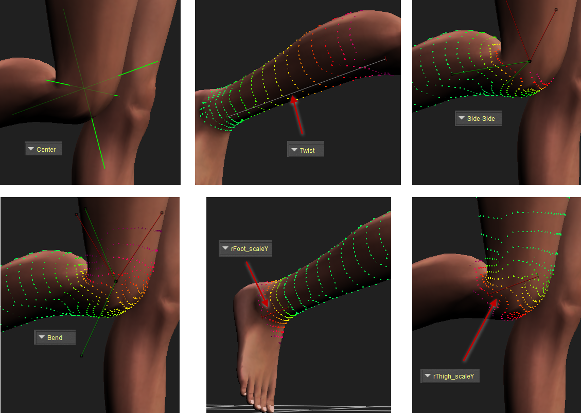
Joint Attribute Indicators.
Joint Strength Indicators
The Joint Editor allows you to control joints and blend zones. Blend zones define how the area that transitions from one joint to another react when they bend, twist, or rotate. As you work in the Joint Editor, you will notice that the selected body part is covered with different colored dots. The color of these dots represent where a joint parameter or falloff zone has the most amount of effect.
In the figure shown below, a figure’s right thigh is selected as the current body part, and the Bend parameter is the parameter that is being edited. The joint is placed at the right knee. Notice the multi-colored dots which show how the joint affects the selected body part:
- Bright green dots appear where the joint or zone has the greatest effect. In other words, when you bend the right shin, the entire area that is covered with green dots will be affected by the bend.
- Yellow dots appear where there is a blend between the moving part (the shin) and the stationary part (the thigh). In other words, when the right shin is bent, the polygons that are highlighted with yellow dots will stretch or squash or skew to make the transition as smooth as possible.
- Red and darker dots appear where little or no effect occurs. In other words, when you bend the right shin, the right thigh (which is above the shin) will not be affected.
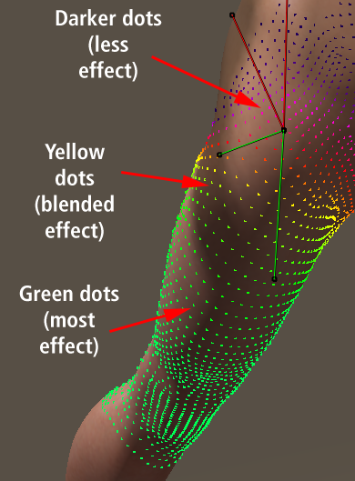
The strength of a joint is represented with multi-colored dots.
Editing Joint Parameters
To edit a joint’s parameters:
- Select the desired joint in the Pose Room.
- Choose Window > Joint Editor to open the Joint Editor.
- Use the Selection menu to choose the attribute that you want to edit. Each joint will have several parameters and will include some of the following: Center, Twist, Bend, Side to Side, Front to Back, or Up and Down. These attributes are further described in Joint Attribute Types.
- Use the Falloff Zones section to add additional deformers that can affect the selected attribute. If no deformers exist, click the Add button to add one or more. You can add one of three types of transformers: Spherical, Capsule, or Weight Map. These will be described further in Creating and Using Falloff Zones.
- The section beneath the Falloff Zones section shows numerical values for the currently selected joint attribute. You can either change these values manually, or by making adjustments to the deformers in the document window. For example, if you are displaying the Twist attribute, you can enter values for Twist Start and Twist End in the Joint Editor, or you can click and drag the ends of the Twist indicator in the document window to make adjustments visually.
- If the joint attribute allows, optionally enter Bulge Settings that make the selected body part bulge more realistically when the parameter is adjusted. These are discussed in Editing Bulge Settings.
- Set the Joint Order as described in Setting Joint Orders.
- When you are finished setting all of the joints, you can use the Zero Figure button to return the character to its default position, and then save the figure to your library.