Step 2: Loading and/or Creating Bone Structures
This section describes what bone structures are, what they do, and how to create/modify a bone structure for your imported geometry or figure.
About Bone Structures
Each Poser figure includes hierarchy and joint information that together determine how the figure behaves when posed. The Setup room expresses this information as a bone structure or skeleton that is tailored to each figure. Skeletons are a critical part of your figures because they define where and how the figure bends, just as your own bones define how and where you bend. Skeletons provide the following information for each figure:
- Defining the figure’s hierarchy: The skeleton defines the parent/child relationships in your figure. Please refer to Poser Figures Hierarchy for information about hierarchies within Poser.
- Locating joints: Just as with your own skeleton, your figure will only bend at joints, which are the places where bone ends meet.
- Limiting figure movement: By now, you are keenly aware that each joint in your body has a limited range of motion under normal circumstances. For example, your elbow only bends in one direction and cannot flex beyond straightening your arm out, your wrist can move in any direction within a narrow cone, and so forth. You can define limits for each of your figure’s joints. These limits can prevent you from creating unnatural looking poses, one part of the figure crossing through another part, etc.
- Figure resolution: The more bones your figure’s skeleton has, the greater degree of flexibility (resolution) it will have. For example, the Andy figure allows you to bend the shoulder, elbow, and wrist, but not the palm or fingers. By contrast, the Ryan figure lets you adjust the precise position of each finger.
- This image shows Andy’s left hand and underlying bone structure on the left, and Ryan’s left hand and bone structure on the right. Note that Andy has only one bone to define his entire hand, while Ryan has a far more realistic bone structure complete with palm and fully articulated finger joints.
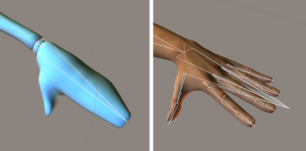
Bone structures of a simple hand and a more complex human hand.
Bones appear as light gray pyramids with the bases pointing towards their parents and the tips pointing towards the children. Selected bones appear red.
About Creating a Bone System
There are two basic scenarios for creating or editing a bone system:
- Modifying an existing figure: If you have a figure loaded when you enter the Setup room, the current figure’s normal bone system will automatically be loaded, and the separate body parts will be combined into a single object for easier manipulation while in the Setup room.
- Creating a new figure: You enter the Setup room with a geometry (prop) selected. You can then load a bone structure from an existing figure by selecting the desired figure in the Library palette and clicking the Change Figure button. Or, you can use the Bone tool to create a fully customized bone system. You can also combine these methods by loading a bone structure and using the Bone tool to make modifications. The Bone tool appears in the Setup room workspace with the other Editing tools.
![]()
The Bone Tool.
The following sections discuss selecting a bone system for your geometry and using the Bone tool.
Selecting the Proper Structure
The quickest way to define a bone structure for your new figure is to load the bone structure of a figure that resembles your current object as closely as possible. For example, the simple geometry shown below does not require a high-resolution bone structure, since it does not have fingers or other detailed features. If you are creating an animal figure, you should probably load an animal figure’s bone structure. The basic idea is to minimize the amount of work you have to do.
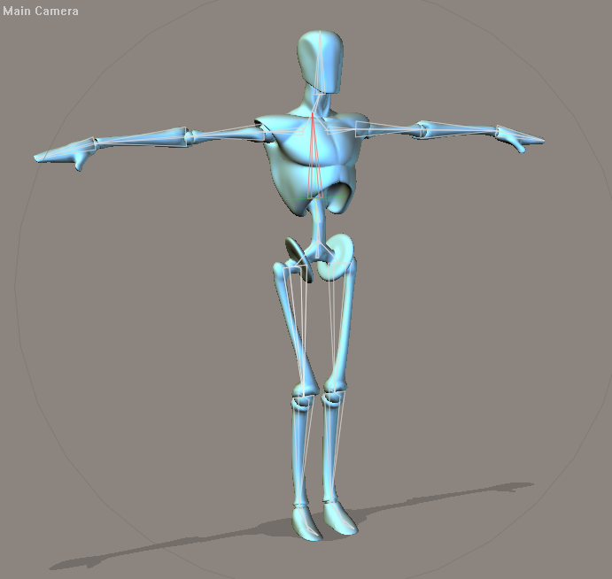
Selecting an appropriate bone structure.
In the above graphic, the positions of the bones match the corresponding portions of the geometry. If the skeleton does not match the figure, you can position the bones as discussed in Positioning_the_Bones.
Inserting & Deleting Bones
The Bone tool lets you create bones, either within a bone structure or from scratch. To create a bone, click at the point where you want the bone to begin (base) and drag to where you want the end (tip). You can fine-tune the bone’s position and parameters later, so you do not need to worry too much about being perfect.
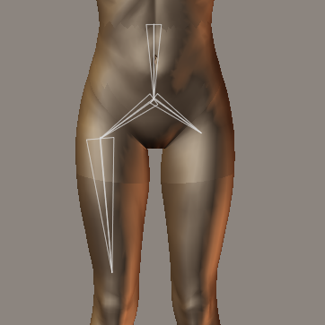
Adding bones to a figure.
New bones are created as children of the most recently selected or created bone. You can select a previously created bone (or any bone in the skeleton) and add new child bones by single-clicking the bone you wish to use as a parent and then clicking and dragging to create a new bone as described above.. The graphic shows a new bone inserted between the hip (parent) and thigh (child).
Bones can be selected as follows:
- In the Hierarchy or by clicking on the bone with the Bone tool selected
- Via the Actor selector in either the Properties palette or the Setup room Preview tab
To delete a bone, simply select it and press [DEL].
Positioning the Bones
Now that your bone structure is built to match your geometry, the next step is to align the bones with the geometry. Unless you have already built a bone structure for a figure and have simply tweaked the geometry slightly, the chances are that the default bone positions will not line up with the geometry, as shown in the graphic on the right. The figure on the left illustrates the effects of having a bone structure that is not positioned according to the geometry, while the figure on the right demonstrates proper figure behavior.
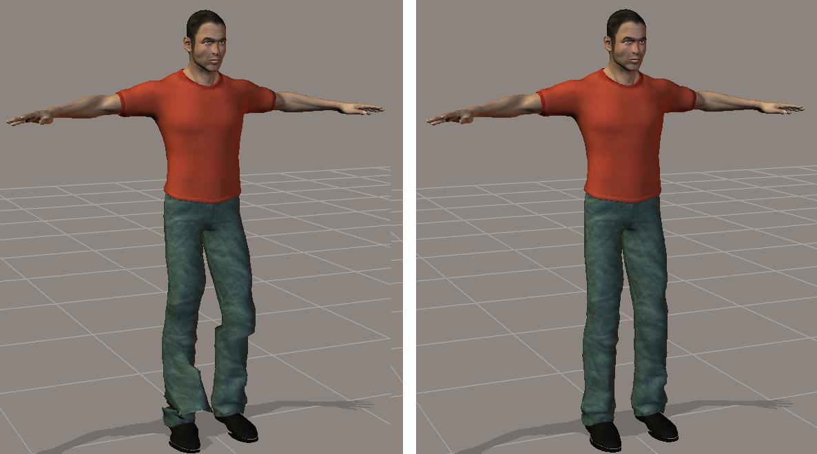
When bones are not positioned correctly, body parts can appear distorted.
You can position bones using any of three methods:
- Select one of the available Editing tools (Rotate, Twist, Translate/Pull, Translate In/Out, or Scale) and position the bones using the mouse.
- Use the Joint Editor palette to precisely position joints.
- Use the Rig Symmetry control (see Positioning_Bones_Using_Rig_Symmetry) to position the bones on the opposite side of the figure.
You will probably use a combination of all three methods as you work to position the bones on your geometry. The following sections discuss each of the three methods in detail.
Positioning Bones With the Mouse
You can position bones with the mouse in one of two ways:
- Selecting the desired Editing tool followed by clicking in the middle of a bone uses the selected tool to modify the position of both the selected bone, all of its children, and all joint settings for both the current bone and all children (including falloff zones). This Selecting, clicking and dragging into position is the preferred method.
Please refer to Creating and Using Falloff Zones for an explanation of falloff zones.
- Clicking near the beginning or end of a selected bone allows you to translate just the selected endpoint regardless of the selected Editing tool. The mouse pointer changes to a bull’s eye when you select a bone and place the pointer near the beginning or end of the selected bone, as shown.
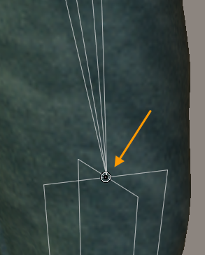
Adjusting bone placement.
When editing bone endpoints, joint settings such as falloff zones are not adjusted. This method is good for making minor adjustments once the bones have been placed near their final positions. After you have properly aligned the skeleton to the geometry, you can adjust the falloff zones further. Please refer to Creating and Using Falloff Zones for an explanation of the various types of falloff zones.
When positioning bones using the mouse, you should use one of the orthographic cameras (Left, Right, Top, Bottom, Front, Back) to ensure that you are only positioning them in one plane at a time. Alternatively, you can use the Document’s multiple pane view to position the bones in 3D space.
Positioning Bones With the Joint Editor Palette
In addition to (or instead of) using the mouse to position bones, you can use the Joint Editor palette by selecting the bone you wish to edit. Please refer to Working with Joints and Weights for complete information on using the Joint Editor palette.
Positioning Bones Using Rig Symmetry
Assuming your imported geometry is symmetrical, you can drastically reduce the amount of time it takes for you to position bones by positioning only those bones on half of the geometry and then using the Figure > Rig Symmetry commands to automatically position the rest of the bones.
The Symmetry functions involving arms, legs, and the torso only work when the bones in those regions have been named and grouped so as to belong to the selected areas of the geometry. If you have loaded an existing bone structure for use with your current geometry, the bones will already be named for you.
Limits will be copied when using the Rig Symmetry command (non-custom symmetry only).
There are several different options for Rig Symmetry:
- Left to Right: Copies rig settings from the entire left side to the right side.
- Right to Left: Copies rig settings from the entire right side to the left side.
- Left Arm to Right Arm: Copies rig settings from the left arm to the right arm.
- Right Arm to Left Arm: Copies rig settings from the right arm to the left arm.
- Left Leg to Right Leg: Copies rig settings from the left leg to the right leg.
- Right Leg to Left Leg: Copies rig settings from the right leg to the left leg.
Custom: Allows you to configure custom rig symmetry settings. Press Custom to open the Apply Custom Figure Symmetry dialog described in Applying_Custom_Rig_Symmetry.
Applying Custom Rig Symmetry
The Custom Symmetry dialog allows you to selectively apply rig symmetry on any combination of body parts, and to apply symmetry across a specified number of frames in an animation.
Choose Figure > Rig Symmetry > Custom to open the Apply Custom Figure Symmetry dialog. This dialog allows you to select body parts on which rig symmetry can be applied. The options in the Apply Custom Figure Symmetry dialog are as follows:
Apply Custom Figure Symmetry dialog.
- Left to Right: Choose this option to apply the values from the left side of the figure to its right side.
- Right to Left: Choose this option to apply the values from the right side of the figure to its left side.
- Apply Symmetry To: Allows you to specify the type(s) of symmetry that you are applying.
- Limits: Check this option if you want to copy limit settings from one side of the figure to the other.
- Joint Setup: Check this option if you want to apply joint settings (translation or rotation, weights, etc.) from one side of the figure to the other.
- Hierarchy Window: Check or uncheck the body parts that you want to include in your Custom Symmetry action.
- Select All: Selects all items in the hierarchy list.
- Select None: Deselects all items in the hierarchy list. Allows you to ensure that all items are deselected before you select specific items to include.
- Cancel: Exits the Apply Custom Figure Symmetry dialog without applying the settings.
- OK: Click to apply your choices to the selected figure.